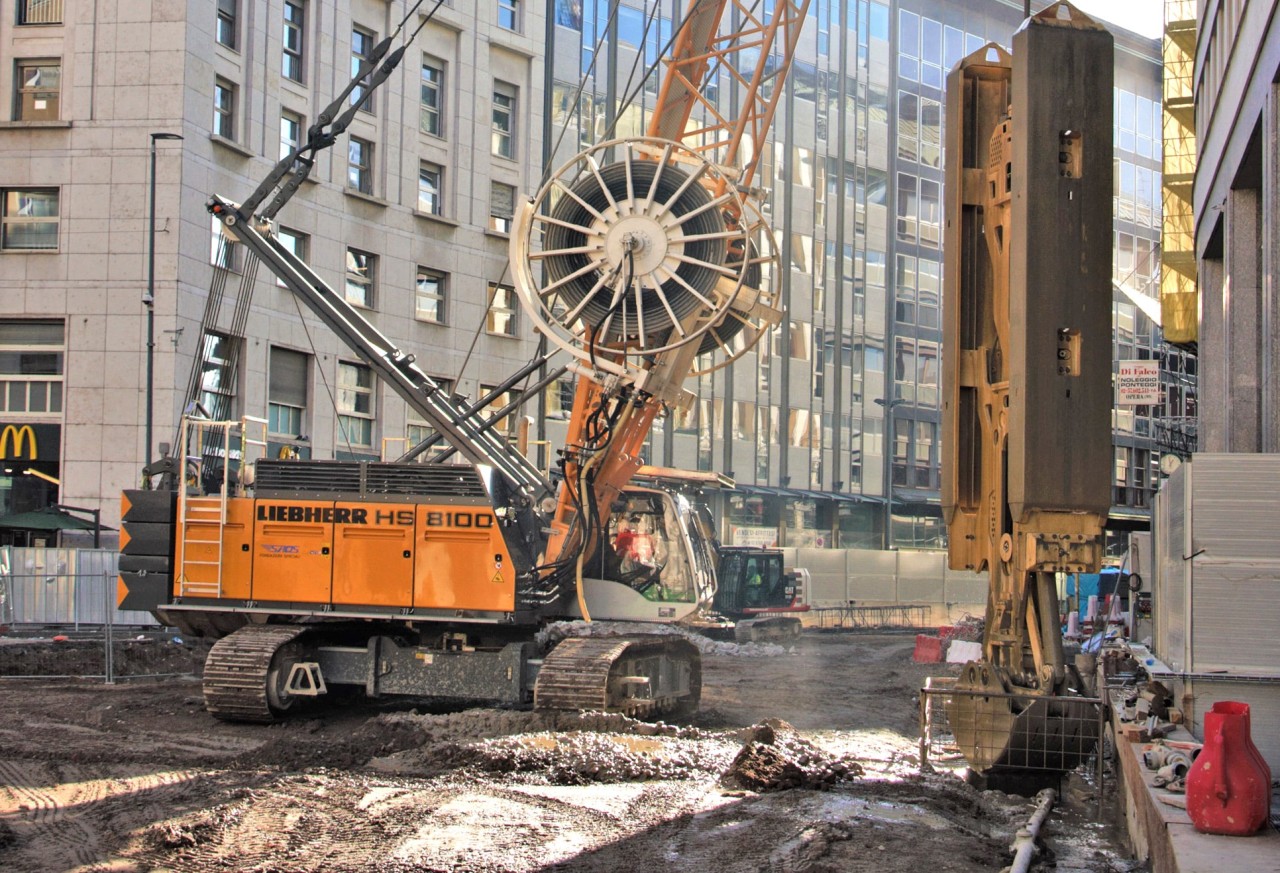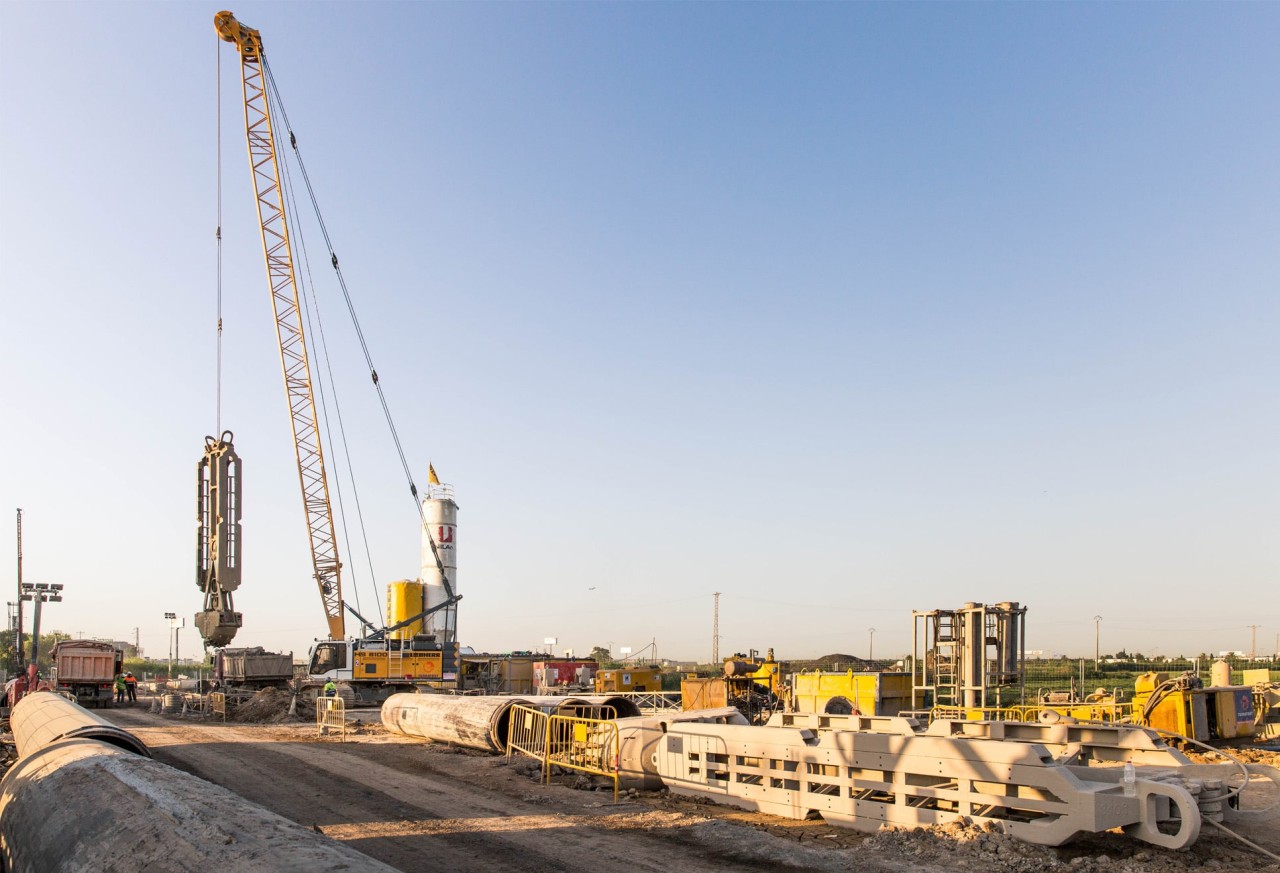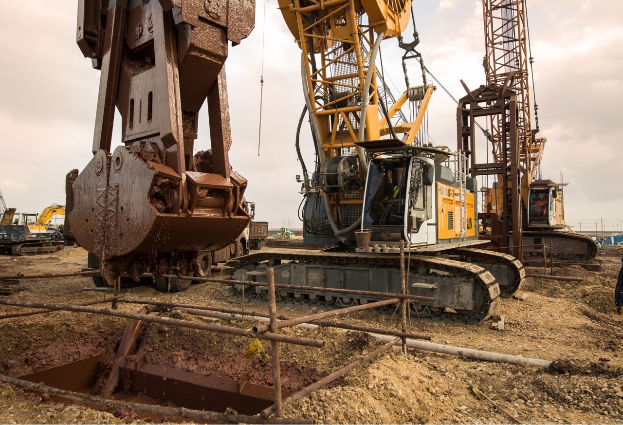


Slurry wall grab
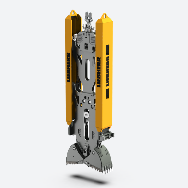
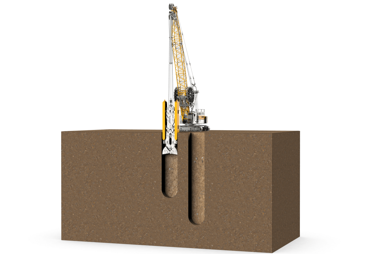
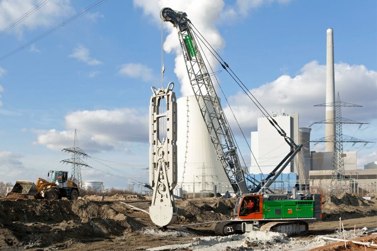
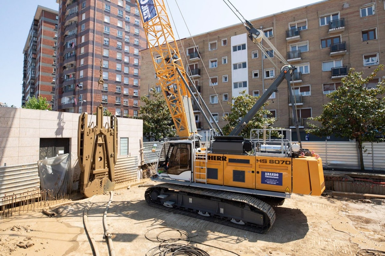
If slurry walls are installed with a grab, a two-jaw slurry wall grab suspended on a duty cycle crawler crane excavates the slurry wall panels. Mechanical grabs are opened and closed via rope, hydraulic grabs via hydraulic cylinders. Hydraulic grabs can additionally be fitted with flexible guiding strips on the grab frame which allow to align the grab within the trench.
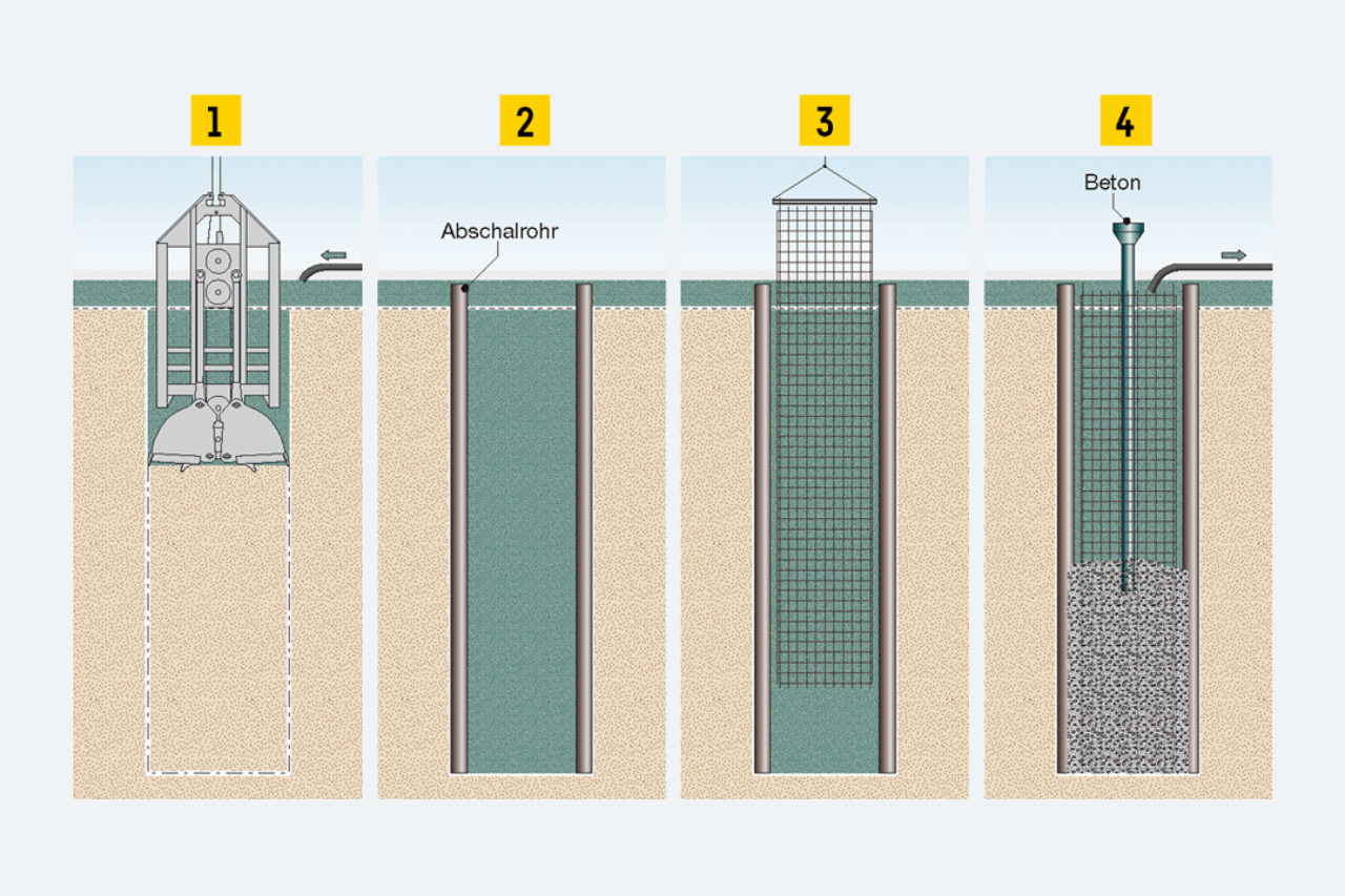
Production steps of a slurry wall panel made of reinforced concrete

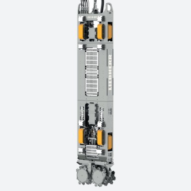
Hydraulic slurry wall grab


01/07
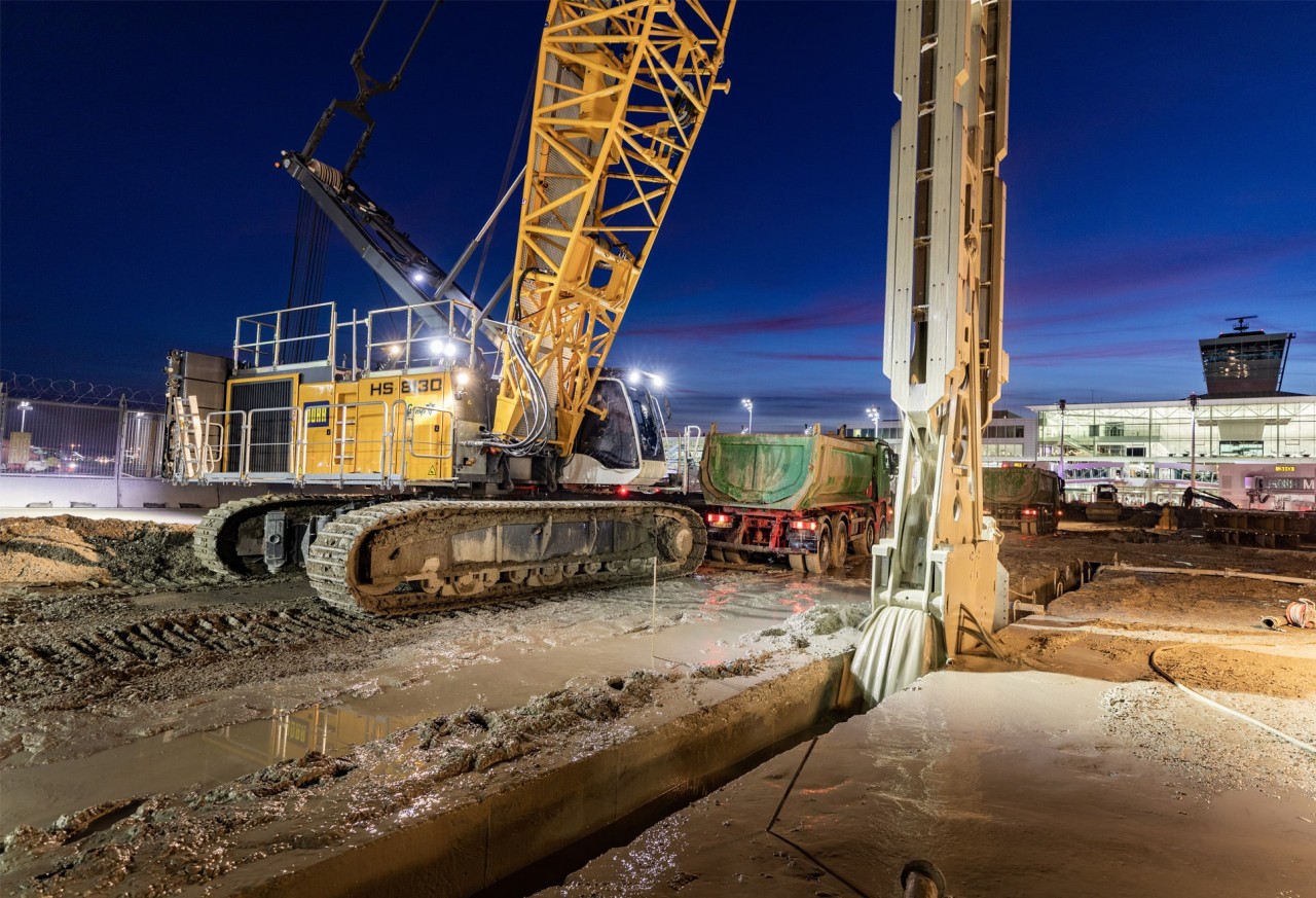
Video: Slurry wall grab
Duty cycle crawler cranes from Liebherr excavating slurry walls with mechanical or hydraulic slurry wall grabs.
Machines
Results 1–6 of 7
1
2